 |
Il programma BURBON
Camillo Trevisan trevisan@iuav.it
Il programma
BURBON consente di generare
prospettive "solide" - o
di contro-deformarle in modelli regolari -
definendo un modello tridimensionale DXF, un Punto
di Vista, un Punto di Fuga
ed un Piano delle tracce (Quadro).
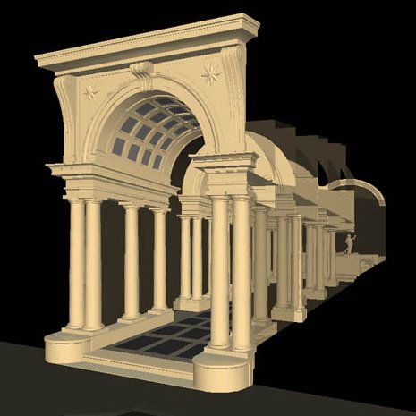
A sinistra, la rappresentazione
della galleria prospettica del Borromini a Palazzo Spada,
Roma (rendering E. Garbin, LAR, IUAV).
|
Le entità da proiettare sono contenute in un file di tipo DXF di grandezza
indefinita.
Vengono proiettate le entità i cui punti appartengono ai gruppi DXF
10..17 (per la coordinata X dei punti che definiscono le entità stesse), 20..27
(Y), 30..37 (Z).
Possono dunque essere proiettate 3Dfacce, linee, punti, polilinee
3D (fare riferimento al manuale AutoCAD per l'identificazione
completa delle entità trasformabili).
Non saranno trasformate correttamente le entità arco e cerchio,
che dovrebbero essere approssimati con polilinee 3D.
Nel caso di 3Dfacce sarà poi possibile eseguire con successo il comando
NASCONDI (HIDE).
Le entità Mesh e i blocchi devono essere "esplosi"
ripetutamente per ottenere le singole entità primitive che li compongono.
Per trasformare solidi e regioni (versione 13 e successive) è necessario esportarli in
formato 3DStudio (comando 3DSOUT, usando i parametri di default), e
importarli nuovamente in AutoCAD con il comando 3DSIN. Le entità importate, una volta
"esplose", saranno nella forma di 3Dfacce e pertanto risulteranno
trasformabili.
Tuttavia, in questo caso, potranno comparire linee di
tassellazione e spigoli di facce che in realtà non dovrebbero essere visibili.
Per renderle invisibili usare il comando EDGE.
Il programma BURBON (che prende il suo nome da Guidubaldo
Burbon del Monte) opera nel modo seguente:
- Viene prima costruito il modello regolare tridimensionale
(salvato nel formato DXF) composto da facce
(preferibilmente), polilinee 3D, punti, linee, ecc. Il
modello sarà posto nello spazio in modo da avere il suo
asse (l'asse che collegherà il Punto di Vista al Punto
di Fuga) parallelo all'asse Y.
- Dal menu Proietta del programma BURBON si
attiva il comando Proietta modello 3D...
- Verrà chiesto di inserire il nome del file di ingresso
(file di tipo DXF); il file di uscita (contenente il
modello trasformato dal programma) e le coordinate del Punto
di Vista (X, Y, Z), del Punto di Fuga (solo la
coordinata Y, poiché le coordinate X e Z saranno le
stesse del PV) e del Quadro o Piano delle
tracce (anche in questo caso solo la coordinata Y,
poiché il Quadro è considerato parallelo al
piano XZ). Il PV ed il PF non devono coincidere tra loro,
né essere posti sul Quadro. La retta PV-PF è
parallela all'asse Y e ortogonale al Quadro. Sul Quadro
il modello di partenza e di arrivo coincidono.
- Se è attivato il segno di spunta sulla voce Deformazione
del modello (menu Proietta), il
modello regolare di ingresso verrà deformato nella
prospettiva solida di uscita. In caso contrario (assenza
del segno di spunta, ottenuta selezionando il comando
stesso), il modello deformato di ingresso verrà
contro-deformato nel modello regolare di uscita.
- Se è attivato il segno di spunta sulla voce Scrivo
punti su file (menu Proietta), il
programma creerà un file in formato ASCII (avente lo
stesso nome base del file di uscita e suffisso CDR)
contenente le coordinate di partenza e di arrivo di tutti
i punti trasformati.
- Poiché il programma genera automaticamente un file ASCII
(avente lo stesso nome base del file di uscita e suffisso
PRM) contenente i parametri di trasformazione prospettica
(coordinate PV, PF e Quadro), sarà possibile
richiamare successivamente un tale file mediante il
comando Carica parametri... (menu Proietta).
- Il programma genera o aggiorna automaticamente anche un
file ASCII (avente lo stesso nome base del file di
ingresso e suffisso HST), contenente la sequenza di tutti
i valori usati dal programma, partendo da quel file di
ingresso: sarà così possibile ricostruire facilmente le
varie prove eseguite sullo stesso modello di partenza.
- Il file compresso comprende anche un modello DXF di
esempio, contenente il modello 3D, assai semplificato,
della galleria regolare ideale relativa alla
Galleria prospettica di Palazzo Spada, a Roma (cfr. AAVV,
Atti delle conferenze...)
The programme
BURBON allows you to generate models of solid perspectives – or to
counter-deform them into regular models – defining a three-dimensional model
DXF, a viewpoint, a vanishing point and a plane of the traces.
The entities of the starting model are contained in a file type DXF of infinite
size. The entities with points belonging to the group DXF 10..17, 20..27, 30..37
are modified. However, 3D faces, lines, points, 3D poly-lines, traces, texts
etc. may be transformed. The blocks, the Mesh entities and the AME solids must
be “exploded” repeatedly to obtain the individual primitive entities
constituting them. In the case of the solids (only for the releases 11 and
12 of AutoCAD) it is advisable to apply the MESH command before “exploding”
them; this enables you to obtain 3D faces and not simple lines. In this manner,
once the deformed model has been brought back to AutoCAD, the hidden lines can
be cancelled, applying the command HIDE. It should be noted that, in the
“explosion” of the solids, AutoCAD (from version 13 on) produces entities of
a Body type, which cannot be correctly transformed by the programme rather than
lines or 3D faces. In this case use the 3DSOUT command and 3DSIN, to obtain
3DMESHes from solid. Explode them to obtain 3DFACEs.
The programme BURBON (given its name by Guidubaldo Burbon dal Monte) works in
the following way:
- First the user constructs a regular three-dimensional model (which should be
memorised in the DXF format, version 12), made up of faces (preferably), 3D
poly-lines, points, lines etc. The model is then placed in space so that its
axis (the axis that is to connect the view point with the vanishing
point) is parallel to the Y-axis.
- Selecting Proietta from the BURBON menu the command Proietta modello
3D is activated.
The name of the file of entry will have to be inserted (file of type DXF); the
exit file (which will contain the model transformed from the programme) and the
coordinates of the view point PV (X, Y, Z), the vanishing point PF
(only
the Y coordinate, since the coordinates X and Z will be the same as the PV) and
of the plane of the traces (also in this case only the coordinate Y,
since the plane is considered to be parallel to the plane XZ). The PV and the PF
must neither coincide (amongst themselves) nor be placed on the plane of the
traces. The line PV-PF is parallel to the Y-axis and orthogonal to the plane
of the traces. On this plane the starting and end model coincide.
- If the signal Deformazione del modello is activated on the option (menu
Proietta),
the regular starting model will be deformed in the solid perspective of exit
(direct deformation). In the opposite case (absence of signal, obtained by
selecting the command itself), the deformed starting model will be
counter-deformed into a regular model of exit (inverse deformation).
- If the signal on the option Scrivo punti su file (menu Proietta)
is activated, the programme will create a file in the ASCII format (with the
same base name of the exit file and the suffix CDR) containing the initial and
final coordinates of all the transformed points.
- Since the programme automatically generates an ASCII file (with the same base
name of file of exit and suffix PRM), containing the parameters of perspective
transformation (coordinates PV, PF and plane of the traces), it will be
possible to successively recall such a file using the command Carica
parametri… (menu Proietta).
- The programme also automatically generates or up-dates an ASCII file (with the
same base name of file of entrance and suffix HST), containing the sequence of
all the values used by the programme, starting from the entrance file: in this
manner it will be easily possible to reconstruct the various tests carried out
on the initial model.
The programme (including these instructions in HTM format and a DXF example
file, containing a model of the ideal regular Gallery which has been simplified
and illustrated in section 2) is found in the CD-Rom, in the file BURBON.
To obtain the solid perspective closest to the real Gallery of Palazzo Spada
from the example model, the file BASE.DXF must be indicated as entry file; the
following values must be used as parameters of transformation, already indicated
in section 2:
X PV = 0.0; Y PV = -5.6666; Z PV = 6.6666; Y PF = 69.6666; Y perspective
plane = 0.0.
Bibliografia:
- Rocco Sinisgalli, Una storia della scena prospettica, dal
Rinascimento al Barocco. Borromini a quattro dimensioni,
Cadmo, Firenze 1998.
- AAVV, Atti delle conferenze
del ciclo "Prospettiva e Prospettive", curato dal
prof. Rocco Sinisgalli. In corso di pubblicazione per i tipi
della Cadmo.
Visitatori dal 02/05/2000


